Advanced Outline Layer
Under construction! See Advanced Outline Layer Talk page
![]()
About Advanced Outline Layers
To create an Advanced Outline Layer use the Spline Tool and check "Create Advanced Outline" in the Tool Options Panel. Once you finish the definition of the geometry of your outline and after pressing the "Make Spline" button (or selecting another tool or state) you create the Advanced Outline Layer with the current "Outline Color".
Depending on the options you choose in the Tool Options Panel other Tools like Star Tool or Circle Tool can also create Advanced Outline Layers.
Using the Layer Menu "Make Advanced Outline", "Make Outline" or "Make Region" commands you can also create those layers.
Differences with Outline Layer: Outline width
The width Handle defines the outline width at a particular place.
In the regular Outline Layer, each width Handle is connected to the vertex that defines the outline shape at that place. That means that the user needs to insert a new vertex on the Spline every time he wants to change the outline width in some place. This behaviour can cause problems when the shape of the outline is very simple but the width varies a lot.
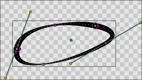
Practice shows that most of the time the user wants to specify the width independently from the placement of Spline vertices. Such functionality is available in the Advanced Outline layer, which Handles its width in a different way: the width Handles are freely moved around the Spline and define its width at any point.
Features
Advanced Outline introduces some features to the regular outline, as shown in this Advanced outline demo video. They are listed with examples below:
No need to place a vertex to change the width
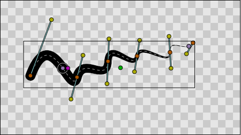
The width is controlled just by two points, while the Spline is constructed of many vertices
Different types of tips: Rounded, Squared, Peak, Flat.
Segmented outline
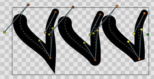
Three global cusps types: Sharp, Rounded, Bevel.
Control of smoothness from linear (0.0) to smooth (1.0)


Parameters of Advanced Outline Layers
The parameters of the Advanced Outline Layers are:
| Name | Value | Type |
| 0.000000 | real | |
| 1.000000 | real | |
| Composite | integer | |
|
|
color | |
| 0.000000u,0.000000u | vector | |
|
|
bool | |
|
|
bool | |
| 0.000000pt | real | |
| Fast Gaussian Blur | integer | |
| Non Zero | integer | |
| List | list (Spline) | |
| 2.000000pt | real | |
| 0.000000pt | real | |
| Rounded Stop | integer | |
| Rounded Stop | integer | |
| Sharp | integer | |
| 0.500000 | real | |
|
|
bool | |
| List | list(WPList) | |
|
|
bool | |
|
|
bool | |
| List | list(WPList) | |
| 0.000000u | real |
Specific parameters for Advanced Outline Layer
This section lists only the parameters specific to the Advanced Outline Layer. For documentation about the other parameters, refer to Outline Layer.
- Tip Type at Start
- Tip Type at End
- Cusps Type
- Smoothness
- Width Point List
Tip Type at Start / End
As with width points, the end and start of the unlooped Advanced Outlines has a type of tip defined. The user can choose between the same types of tips as for a width point. When the first/last width point has its before/after interpolation type set to Interpolate the start/end of the outline is rendered using the Tip type at start/end parameter.
Those parameters don't have any effect if the Spline is looped or the first/last width point has its before/after interpolation type set to anything but Interpolate. In that case, the segment between the start/end width point and the start/end of the Spline is not rendered.
The types of tips are the same as the width point tip types except that it doesn't offer the Interpolate type because it would not make sense:
Parameters:
| Tip Type | Example |
|---|---|
| Rounded | 
|
| Squared | 
|
| Peak | 
|
| Flat | 
|
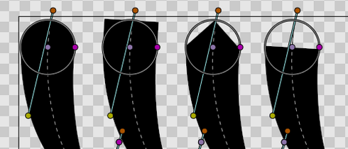
Cusp Type
There are three types of cusps in the Advanced Outline:
Parameters:
| Cusp Type | Example |
|---|---|
| Sharp | 
|
| Rounded | 
|
| Bevel | 
|
The type of cusp is controlled for the entire layer so currently it is not possible to control the type of corner individually. Maybe in future versions it will be possible.
Smoothness
The Smoothness controls how the width is calculated between widthpoints. The width at a position p is a function of the surrounding width points. When smoothness is zero interpolation is lineal, when smoothness is 1.0 interpolation is given by a 5th degree smooth Spline.
Homogeneous
Enabling "Homogeneous" changes the way the position of the width points change according modification of the outline.
- When false, the "Position" parameter for a width point is equally distributed among the vertices. For example, in a spline with five vertices, "Position" values of 0, 0.25, 0.5, 0.75, and 1 correspond to the first, second, third, fourth, and fifth vertex, respectively, regardless of how close or far apart those vertices are. Between vertices, the "Position" parameter is based on spline length.
- When true, the "Position" parameter increases smoothly from the start to the end of the spline based on the length of the entire spline. This means a "Position" of 0.5 will always correspond to the halfway point of the spline, not to a particular vertex.
Width Point List
Each Advanced Outline has a list of parameters that represent the information for each width item. They are called Width Points and consist of four sub-parameters:
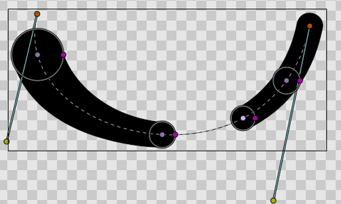
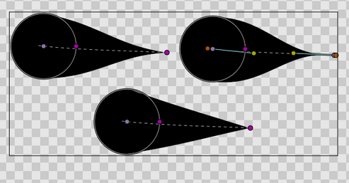
- Position (Real number): represents the position of the width point along the Spline. Although it is allowed to be any real number, its meaning is only from 0.0 to 1.0. 0.0 corresponds to the start of the Spline (first Spline point on the Spline list) and 1.0 to the last Spline point. For looped Splines 0.0 and 1.0 are equal. The position is represented by the light purple Handle that always lies on the Spline. The point on the spline corresponding to a particular "Position" value is affected by the "Homogeneous" parameter, explained above.
- Width (Real number): It is the width multiplicator of the global Width parameter of the Advanced Outline Layer on the position given by the Position parameter. The final width is calculated multiplying the global Advanced Outline's Width (W) by the Width of the widthpoint (w) and adding the Expand parameter (E). Calculated width = W*w+E
- Tip Side Before/After: Those two sub-parameters controls how the width is interpolated before and after the current widthpoint. The sub-parameter can have four values:
- Interpolate: Between the previous/following width point, the width is calculated by interpolation based on smoothness value.
- Rounded: There is a rounded tip that points to the width point before or after. If the previous/following width point is "Interpolate" on its posterior/previous side it considers that the width of the widthpoint in question is zero just before/after it. If the previous/posterior width point is other than "Interpolate" then the segment between those two width points is empty. See examples to understand it fully.
- Squared: Same as Rounded but using square tip.
- Peak: Same as Rounded but using peak tip.
- Flat: Same as Rounded but using flat tip.
The Width Point list has one internal non-animatable parameter called "loop". You can reach it by right clicking the Width Point List parameter. If the Width Point list is unlooped, then any width point that has a Position outside the range of [0,1] is clamped to (brought within) that range. For example: a Position = 1.35 is clamped to 1.0 then the Width Point List is unlooped. Otherwise, if the Width Point List is looped and a width point has a Position of 1.3, its modulus based on the range [0,1] is used, so it is turned to a position of 0.3.
Fast
...TODO WriteME.about...
Dashed Outline
...TODO WriteME.about...
Working with the Avdanced Outline
Creation of the Advanced Outline
You can create Advanced Outlines by various ways:
- With the Draw Tool (check Create Advanced Outline in the tool options).
- With the Spline Tool (check Create Advanced Outline in the tool options).
- Using a Geometry Layer (check Create Advanced Outline in the tool options).
- With the menu "<Insert> → <Layer> → Geometry → Advanced Outline".
Change the width of the Width Points
Initially the width Handles are hidden. You can make them visible by pressing (Alt5) or clicking on the width toggle button. It is possible to change the width using the Width Tool using the same procedure as for regular outlines. If you want more control over the width you can modify the width Handles with the Transform Tool (AltA). More fine tunning is possible by expanding the width point sub-parameter and entering a specific value for the Width sub-parameter. In that case negative values are allowed to produce nice effects.
Change the position of the Width Points
When you make the width Handles of the width points visible/invisible, the position Handles also become visible/invisible. This way, the user has a single way to hide/show the position and width Handles.
|
Change the position of the Width Points This may change in the future
|
The position Handles of the width points can be modified using the Transform Tool (AltA) and clicking and dragging the position Handle. You will notice that Handles are tied to the Spline so once clicked and dragged they can be placed at any way on the Spline. Notice that if you have a width point position Handle at position 0.2 and you click and drag at position 0.9 it may happen that you obtain a value of -0.1 because you dragged it in one step and the Width Point List may be looped. If you want to avoid those problems do the movement in small steps to indicate the correct path to follow when calculating the new position.
Adding or removing width points
To add a new width point you have to right click on the width point position Handle (purple Handle) to get the context menu. Then select "Add Item (smart)" here to create more width points entries. The width points are created this way:
In the general case, the new widthpoint is created between the width point you click on and the "previous" width point. Depending on the loop status of the Spline, the "previous" width point can be the start of the Spline (unlooped) or the last widthpoint (looped). The worst case is when there is only one width point on the Width Point List. If you add one new item it will lie over the existing one.
The newly added width point will have the interpolated width at the position where it is created.
Specific actions for Width Points
Some needed actions have been added to width points as well as functionality for existing actions for items of the List type parameters. You can reach the list of available actions by right clicking on the width point position or directly on the width point item of the Width Point List. Here are some descriptions of the available actions:
- Convert: Width Points are composite Value Nodes so its natural format is Composite (you can access its components). But you can convert it to other formats. See Convert for details.
- Disconnect: This will disconnect the width point item from the Composite type Value Node. That means that there won't be any Handle to show and that any of its values can be modified. Maybe it is useful for some types of workflows. To restore its Composite status, choose Convert->Composite.
- Insert/ Remove Item Smart: This will add or remove a width point. If Remove is used in animation mode, it will also set the current width point as OFF instead of effectively removing it from the Width Point List. Opposite for the Insert Item Smart.
- Mark Active Point as ON/OFF: You can set width points off to make it not count for width control while the width point is off. When the width point is half on to off or viceversa, the used width point should be the interpolation between the on and off status. But it doesn't work properly at the moment. On / Off values are not interpolated but fully on or fully off. This has to be corrected.
- Export: See Export.
- Loop: When set as looped, as mentioned before, it allows the width point positions loop around the range [0,1].
- Rotate Order: Doesn't do anything.
- Set Side Before/After to: Interpolate, Rounded, Squared, Peak, Flat. Those are shortcuts to do the same as going directly to the sub-parameter and choosing the appropriate Tip Type. Maybe it should be renamed to "Set Tip Before/After".
- Set Width to default/zero: those actions have been added for two reasons. It is very common to want to set the width of a width point to zero. Despite the possibility of use the User Preference of Restrict Radius to First Quadrant, this way it is acceded quickly from the same usual menu. Also when a width point position Handle and a width point width Handle are on top of each other (width = 0) it is hard to modify the width or the position without trouble. To solve this the position Handle has preference over the width Handle in case of coincidence. So access the width Handle it is needed to have a quick action to set it to its default value (1.0).