Generazione Forme
|
Warning! This page contains outdated information. The release of Synfig Studio 0.64.0 introduced new terminology and this translated page needs to be updated according to original English text. You can help updating this page - see instructions here. Thank you! |
Contents
Introduzione
Le primitive di base come i cerchi ed i rettangoli sono sicuramente utili, ma sono anche rigidamente geometrici. Come possiamo gemerare forme più complesse? Possiamo usare lo strumento Linea di Bézier.
Strumento Linea di Bézier - BLinea
In Synfig, la modalità di generazione delle forme è la Linea di Bézier. E' approssimativamente come il "percorso[path]" in altri programmi, ma è strettamente una curvatura [spline] di Hermite.
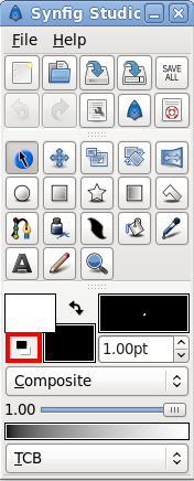
Prima di partire con la lezione sulle BLinee (Linee di Bézier), diamo uno sguardo ad alcuni particolari do come lavora Synfig. Quando clicchi su Strumento BLinea, noterai che i vertici dell'oggetto selezionato (se ve n'è uno) scompaiono, ma il/i piano/i rimarranno selezionati nel Pannello Piani. E' giusto. Tutto quello che genererai con lo Strumento BLinea verrà inserito sopra il piano selezionato. Nota che se vuoi inserire una forma da qualche parte, dovrai selezionare dove lo vuoi prima di selezionare lo Strumento Blinea — variando la selezione dopo verrà selezionato automaticamente lo Strumento Trasforma.Procediamo cliccando su pulsante "Reimposta Colori" nell'angolo in basso a sinistra del gestore dei colori di primo/secondo piano [FG/BG] nella casella strumenti. Questo ripristinerà i colori predefiniti, bianco e nero. Imposta anche ampiezza linea predefinita a qualcosa di tuo gradimento — 10pt è quello che consigliamo.
Dopo aver selezionato lo strumento BLinea, guarda il Pannello Opzioni Strumenti. Accertati che solo "Crea Regione BLinea", "Crea Contorno BLinea" e "Collega Origini" siano selezionati.
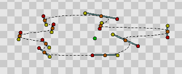
Cliccando con il mouse sulla tela compariranno i vertici. Su un vertice, puoi tirar fuori le sue tangenti trascinando il mouse su esso. Ripetilo più volte, otterrai una Blinea.
Ricorda, tuttavia, che durante questo processo, nulla ti vieta di spostare il vertice in un'altra posizione o di variarne le tangenti. Certo! Se vuoi eliminare un vertice, cliccavi sopra col destro e seleziona "Rimuovi Vertice". Vuoi dividere le tangenti? Clicca col destro su "Separa Tangenti". Vuoi chiudere in un Ciclo Continuo la BLinea? Clicca col destro sul primo vertice su "Ciclo Continuo BLinea".
Condideriamo che la tua BLinea sia come la vuoi. Ottimo. Avrai notato che il piano non è ancora stato generato. Questo perchè siamo ancora in modalità editazione. Ci sono due mogi per generare i piani: passando su un'altro strumento, o premendo il pulsante "Crea" al fondo del Pannello Opzioni Strumenti (è l'icona raffigurante un ingranaggio). Ora, proseguiamo cliccando sullo Strumento Trasforma poichè abbiamo terminato con lo strumento Blinea.
Modifica delle BLinee
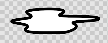
Bene, ora abbiamo una bella area bianca bordata di nero. Avendo selezionato "Crea Regione BLinea" e "Crea Contorno BLinea" nelle fasi precedenti, noterai che abbiamo generato due piani — ilContorno e la Regione nel Pannello Piani. Nonostante i piani siano distinti, i parametri dei loro vertici sono stati collegati — così selezionandone uno e muovendone i nodi anche quelli dell'altro varieranno.
Se vuoi manipolare i vertici dopo aver generato il piano, è veramente facile farlo. Clicca su uno dei piani e fallo. Se vuoi rimuovere un vertice, cliccaci sopra col destro e seleziona "Rimuovi Voce (intelligente)". Vuoi inserire un punto? Clicca col destro sul tratto ove vuoi inserire il vertice e seleziona "Inserisci voce (intelligente)".
|
Nota The only major difference between this normal editing mode and the construction mode is in how you split the tangents — in construction mode you right click on the tangent itself. In normal duck editing mode, you must right click on the vertex that the tangents are attached to. This could be considered a usability bug, and it will be resolved at some point.
|
This may appear to be leading to a mess of layers. And yes, if you aren't using the software properly, that is exactly what you will get. But there is a way to make this more sane. As mentioned in the previous tutorial, you can encapsulate layers into hierarchy.
One quick thing to mention before I finish up. You can change the width of an outline at each vertex. You do this by selecting the outline layer (NOTE: you must select the Outline Layer, the Region Layer has no width data) and tweaking with the width ducks. By default, these are masked. To show them, press Alt5 or click "Toggle width ducks" button at the top of the canvas window (the fifth one from the left). Repeat to hide them again. You can also see other things to mask via the Canvas Menu Caret: "View → Show/Hide Ducks".
Using tablet to draw shapes
If you have graphic tablet you can use Draw Tool to create BLines.
Synfig Studio supports pressure sensitivity, but you need to configure it first. Go to "File → Input Devices..." from toolbox menu. In the Input dialog find your tablet's stylus device and set its mode to "Screen". Click "Save" and then "Close".
Now grab your stylus, create new file and click on the Draw Tool button in the toolbox. Set default line width value to be big enough — say, 15pt — otherwise you will not notice any pressure sensitivity effect. Choose brown as default fill color.
|
Note Steps above should be done with stylus of your tablet, not the mouse. Synfig Studio remembers settings for each input device independently. That's why if you set those options with your mouse device they will not have any effect when you switch to stylus.
|
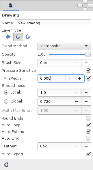
In the Tool Options Panel, make sure that you have same options as shown on screenshot below.
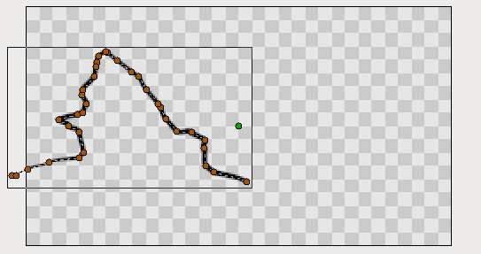
Now let's draw some thing like curvy mountain background. Start drawing a line from the left border to the middle of the canvas. Try to vary pressure while you drawing. Stop near the center of the canvas. This is your first line. Notice new outline layer created in the Layers Panel.
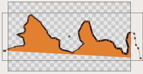
Point your stylus at the last duck of your new BLine and continue drawing to the right border of the canvas. When you finish, look at the Layers Panel again. There's still only one outline layer. Synfig Studio is smart enough to figure out that you don't need a new outline layer and properly extends the last one. You can extend the BLine from both ends, but if you start drawing from any other place of the canvas a new outline layer will be created. Though, your first line will remain selected and nothing stops you to extend it later.
Back to our artwork. At the Tool Options Panel hit the button with bucket icon to fill the outline we just created. A region layer will appear at the top of the layer we are working with. Select outline layer and press "Raise Layer" button in the layers panel to put outline layer on top of the region.
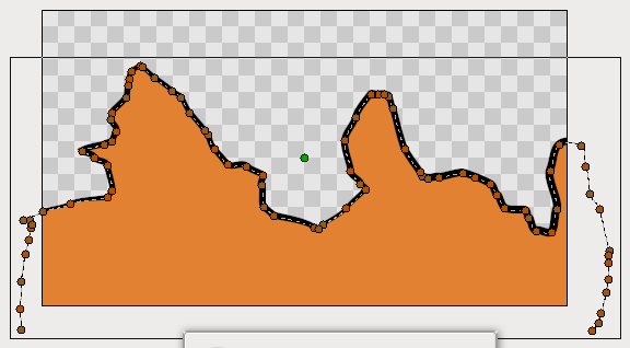
Extend a line from both sides down to the corners of the canvas to make fill appear at the bottom. Great.
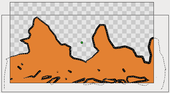
Go ahead and add a few more lines on top of the filled area to give it a mountain-like look. If brown ducks are on your way, you can hide them by clicking the "Toggle vertex ducks" button at the top of canvas window (the second one from the left).
|
Warning! Don't use Alt2 shortcut to turn off visibility of vertex ducks while you using Draw Tool. There's a bug that will cause Synfig Studio to hang.
|
Draw tool is great for drawing complex shapes, but you end up with a bunch of ducks, which are hard to manipulate with the Transform Tool in the way we described above. There are two solutions here.
First, you can increase "Smooth" value in the Tool Options Dialog while using Draw Tool. That will reduce the count of vertices produced at drawing time, but will make your shape less detailed.
Second, you can use Smooth Move Tool to deform existing shape. Go for it and click Smooth Move Tool button in the toolbox. The trick about this tool is that it affects selected ducks only. Press and hold your left mouse button at the empty place of the canvas. Drag to create selection box. Release mouse button when you are done. Or just hit CtrlA to select all ducks. Now you can deform selected segments of BLines. You can change size of influence area by tweaking "Radius" at the Tool Options Panel.
What about outline width? There is a Width Tool for that purpose. It is designed for increasing or decreasing the width of a line much like you would with a pencil on paper. Click Width Tool button on the toolbox, move your stylus over the line you want to change, press and move cursor back and forth along the line, like you scratching something. The width of outline will be increased at the places where you moved the cursor. If you want to decrease the width, just hold "Ctrl" while scratching. Easy!
If you don't want Width Ducks to be displayed, during usage of the Width Tool, just turn them off by pressing "Toggle width ducks" button at the top of canvas window.
|
Warning! Don't use Alt5 shortcut to turn off visibility of width ducks while you using Width Tool. There's a bug that will cause Synfig Studio to hang.
|
Other ways to create BLines
Is that all? Not yet. You can use Circle, Rectangle, Star and Polygon tools to create BLines too. Just check the "Create Outline BLine" and "Create Region BLine" options at Tool Options Panel when using those tools.
Creating geometric primitive as BLine gives you a better control over it's shape and look. For example, if you want a deformed star, then you can use Star Tool to create it as outline and region BLines and then use Transform Tool to deform it.
Now you are ready for the last tutorial in this section. Hang on!
