Warp Layer Layer
m (→Parameters of Warp Layers: formating parameters) |
m |
||
| Line 2: | Line 2: | ||
{{Title|Warp Layer Layer}} | {{Title|Warp Layer Layer}} | ||
{{Category|Layers}} | {{Category|Layers}} | ||
| + | {{Category|Distortions}} | ||
{{NewTerminology}} | {{NewTerminology}} | ||
{{TOCright}} | {{TOCright}} | ||
Revision as of 13:29, 26 February 2017
Somes of the screenshots needs to be updated with 0.64.0
About Warp Layers
The warp layer is a simple but powerful distortion layer. In a few words it takes a rectangular portion of the resulting render of the layers that are behind it and maps the four corners of the rectangle to four arbitrary points in the plane. It is a 2D -> 2D transformation.
To keep the object in place when apply the perspective, you need to set the corners of the perspective destination properly around the object. Notice that the source rectangle must be centered on the object, to achieve a good effect.
If source == destination then object is not warped.
Parameters of Warp Layers
The parameters of the warp layers are:
Source TL
The Top Left corner (vertex) of the source that is going to be mapped.
Source BR
The Bottom Right corner (vertex) of the source that is going to be mapped. Combined with Source TL it defined the "Source rectangle".
Destination TL
The Top Left corner (vertex) of the destination where the source is going to be mapped.
Destination TR
The Top Right corner (vertex) of the destination where the source is going to be mapped.
Destination BL
The Bottom Left corner (vertex) of the destination where the source is going to be mapped.
Destination BR
The Bottom Right corner (vertex) of the destination where the source is going to be mapped.
Clip
When checked (boolean) it only maps the pixels which lie inside the "Source rectangle".
Horizon
For infinite layers (gradients, checkerboard, etc.) it define (Real) where to stop rendering the points of the vanishing point.
- From 0.0 to 1.0 it renders all the points that are backwards on the perspective (in opposite direction to the vanishing point).
- From 1.0 to +infinite it renders the points that go in the same direction of the vanishing point.
High values of Horizon make Synfig spend a lot of time rendering and the result is slightly visibly better.
Some Samples
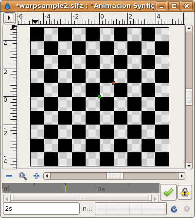
Here are a few sample images of the result of applying the warp layer over a checkerboard layer.
Before distortion:
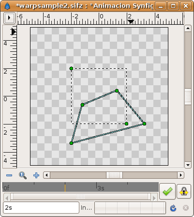
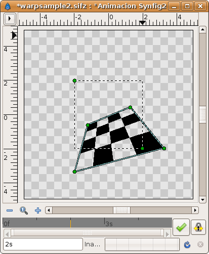
The handles of the warp layer. The dotted lines represent the Source rectangle. Notice how it corresponds to a 4 by 4 section of the checkerboard:
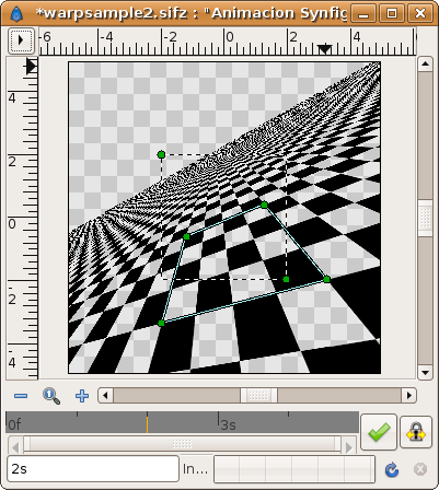
The resulting distortion (horizon = 15.0 and Clip = off). The destination rectangle can be seen to contain the same 4 by 4 section of the checkerboard that the source rectangle contains:
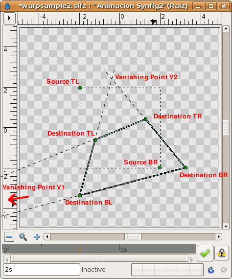
You can see that the rendered horizon is the result of connecting the two vanishing points of the perspective distortion. In this case there are two vanishing points given by the intersection of the lines that connects the following points:
- Intersection of the line that passes by Destination TL point and Destination TR point with the line that passes by Destination BL point and Destination BR point. It gives vanishing point V1 (not shown in the diagram because it is outside the visible area, far off to the left).
- Intersection of the line that passes by Destination TL point and Destination BL point with the line that passes by Destination TR point and Destination BR point. It gives vanishing point V2
Connecting the Vanishing points V1 and V2 gives the horizon line.
See the diagram:
To understand how the Horizon parameter works see this animated image. It moves the Horizon parameter from 0.0 to 30 in four seconds. Notice that from horizon = 0.0 to 1.0 it renders from minus infinite to the current observer position (it is made very fast in the animation, and takes about in 4/30 seconds and most of the time the rendered section is outside the visible area of the canvas - you can see it if you place a zoom out layer on top of them). This means that the portion of plane that is behind the observer point of view is rendered deformed and then very enlarged). Notice too that from horizon = 1.0 to 30.0 it renders the rest of the visible plane. As the horizon parameter gets larger, the final visible horizon gets further away.
The Clip parameter
This image shows what you will get when check it on. Only the pixels from inside the Source rectangle are mapped. In this case, the 4 by 4 section of the checkerboard.
Turning warp on/off
Simply set the destination handles to the same position as the source handles.
